Digital control a switchmode regulators
output voltage
or
Triple resistor fun
Starting Point
Sometimes you need to control a buck (or whatever) converter digitally
or by a remote voltage. This tasks sounds easier than it is in the end.
If you not already know it, then now you do:
The feedback input of a switchmode regulator is very senistive and
prone to pickup noise due to tits high impedance and the (internal)
high gain. Don't caring about it will result in bad regulation and, in
worst case, in oscillating and non-working circuits.
So what must be done ? The feedback path must be as short as possible,
at best, directly put the resistor between the GND and FB pin. But for
hell, how to control it then from external ?
At this point, you can add an additional resistor to your normal
feedback network wich will be layouted as usual.
Now, the feedback divider for the output (and therefore it's AC
components) is the same as standard, and the regulator can work as
normal because there will be no delay or phase shifts inside the
feedback loop. Connecting only a DC voltage (or very low AC) to
the additional resistor will only shift the regulators DC point to
somewhere else.
To control it digital, you can do PWM (see fig. 1) or use a DAC.
Because of the the necessary buffer, you're also able to amplify the
control voltage (if necessary).
See fig. 1 for explanation.
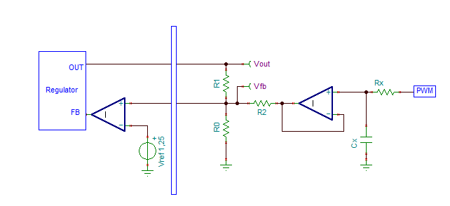
fig.1 Controlling a switchmode
voltage regulator with an external
voltage
It remains the task how we can exactly determine the control voltage we
need.......
Using superposition principle should help here:
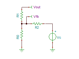
fig. 2 Circuit for mathematical
analysis
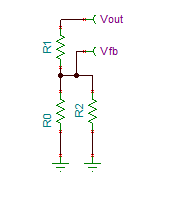
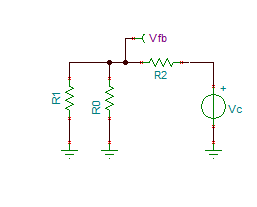
fig 3a (left) and 3b(right) Circuits
for analysis
In fig 3a, the factor
{a} is R0//R2 = R0*R2/(R0+R2),
(1)
in fig
3.b the factor
{b} is R0//R1 = R0*R1/(R0+R1)
(2)
and the output voltages respectively
Vfb1 = Vout * a / (R1+a)
and Vfb2 = Vc * b / (R2+b). (3)
Putting all together,
Vfb = [Vout * a / (R1+a)] + [ Vc * b / (R2+b)]
(4)
In the end, the feedback voltage Vfb is constant (e.g. 1.25V) and Vc
will control Vout.
Simplified
A special case occur if R=R1=R2 and R = N * R0 (R1 and R2 are equal and
N times larger than R0):
V2 = ((N+2) * Vfb) - V1
and
N = ((V2 + V1) / Vfb) -2
Now we rturn to fig. 1 and V1 = Vout and V2 = Vctrl.
Vctrl = ((N+2) * Vfb) - Vout
N = ((Vout+Vctrl) / Vfb) - 2
The maximum output voltage is reached if Vctrl = 0, the minimal output
voltage is reached if Vctrl = max. output voltage.
Between this points the behaviour is strict linear.
Example
See below an example with N = 10 and Vfb = 1.25V.
Maximum output voltage will be 15V @ Vctrl = 0 and minimum output
voltage will be 0V @ Vctrl = 15V.
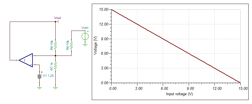
fig.4 Example circuit